
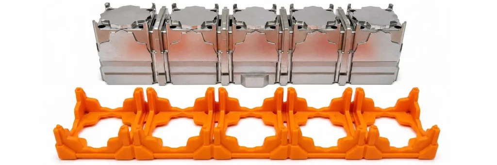
Your prototype works — now what?
You have developed an idea, printed a prototype, and it does exactly what it is supposed to do. The next step is a real plastic part that you can produce in series. That is where a new question arises: is your design actually suitable for injection moulding? Because a shape that comes out of a 3D printer perfectly is not automatically manufacturable in a mould.
That sounds more difficult than it is, because most problems can be solved at the drawing board, long before any steel is cut. A few choices regarding wall thickness, angles and material determine whether your part will ultimately come out of the machine cleanly, reliably and cost-effectively. In this guide, we walk through those choices step by step, in plain language, so you can set up your first part correctly from the start.
Filling, cooling and releasing: where the design rules come from
A mould is a hollow tool that opens again after each cycle. The diagram shows how that cycle works. For your design, what mainly matters is what the plastic has to be able to do along the way: fill the entire cavity smoothly, cool evenly and then release cleanly from the steel.
A 3D printer does not impose these three requirements. A printer builds layer by layer, without a mould that has to open again and without material that has to flow through a cavity under pressure. Every rule of thumb below follows from one of these three principles: filling, cooling or releasing.

The 7 rules of thumb for your design
Seven rules of thumb determine whether your part fills properly, cools evenly and comes out of the mould cleanly. Check them in this order when designing your model.
Wall thickness: uniform and not too thick
The most important rule is a uniform wall thickness. Thick areas cool more slowly than thin ones, and that difference causes voids, sink marks and warping. A solid wall is therefore not stronger, but actually more problematic. Keep the wall roughly the same thickness throughout and hollow out thick sections instead of making them solid.
| Material | Recommended wall thickness |
| ABS | 1.2 to 3.5 mm |
| Polypropylene (PP) | 0.8 to 3.8 mm |
| Polyethylene (PE) | 0.9 to 4.0 mm |
| Polycarbonate (PC) | 1.0 to 4.0 mm |
| POM (Delrin) | 0.8 to 3.0 mm |
| Polyamide (PA, nylon) | 0.8 to 3.0 mm |

Source: Envalior, “Wall thickness”. Rule of thumb: as thin and as uniform as possible; when in doubt, go thinner (“steel safe”).
Need to transition from a thick wall to a thin wall? Do it gradually with a tapered transition, never with an abrupt step.
Rounded transitions instead of sharp corners
Sharp internal corners are weak points. They concentrate stress, which makes the part more likely to break there, and they slow down the flow of the plastic. Therefore, give internal corners a rounded radius. A good rule of thumb is an internal radius of at least half the wall thickness. Also round the outside corner accordingly, so the wall remains the same thickness at the corner and does not become locally thicker.

Ribs instead of solid material
If you want to make a part stiffer, do not thicken the entire wall; add ribs instead. This increases stiffness without the cooling problems associated with thick material. Keep a rib thinner than the wall it stands on, as a guideline 40 to 60 percent of the wall thickness; otherwise, the rib will show on the outside as a sink line. Also give the rib itself a slight draft angle and a radius at the base.

Shrinkage: plastic contracts as it cools down
Plastic shrinks as it cools and hardens, and that shrinkage varies greatly by material. Amorphous plastics such as ABS and PC shrink only slightly and evenly; semi-crystalline plastics such as PP, POM and PE shrink more and are more sensitive to deformation.
You do not need to compensate for that shrinkage in your model yourself. The mould maker makes the mould cavity slightly larger so that the cooled part is dimensionally correct. What you should do, however, is choose your material early and keep the wall thickness uniform, because that is exactly what prevents uneven shrinkage and warping.
| Material | Typical shrinkage |
| ABS (amorphous) | 0.4 to 0.7% |
| Polycarbonate (amorphous) | 0.5 to 0.7% |
| Polyamide (PA, semi-crystalline) | 0.8 to 1.5% |
| Polypropylene (semi-crystalline) | 1.0 to 2.5% |
| POM (semi-crystalline) | 1.8 to 2.5% |
| Polyethylene (semi-crystalline) | 1.5 to 3.0% |
Source: PlastikCity, “Material shrinkage rates”; shrinkage is measured in a standardised way according to ISO 294-4.
Amorphous, crystalline or semi-crystalline?

Plastics differ in how their molecules arrange themselves as they cool, and that determines their shrinkage. Amorphous plastics (such as ABS, PC and PS) have a disordered molecular structure, solidify gradually and shrink only slightly and uniformly. Semi-crystalline plastics (such as PP, PE, POM and PA) form partially ordered, compact crystalline regions as they cool. This ordering takes up less space, causing them to shrink more and more directionally, with a greater risk of warping. Purely crystalline plastics do not exist in practice; the “crystalline” types are always semi-crystalline. Rule of thumb: if you choose a semi-crystalline material, pay extra attention to uniform wall thickness.
Draft angle: why the walls need to be tapered
A part with perfectly vertical walls will not come out of the mould, or will come out damaged. That is why walls are given a slight taper in the release direction: the draft angle. The smoother the desired finish, the smaller the angle can be; the rougher or deeper the texture, the more draft angle you need.
| Finish | Recommended draft angle per side |
| Polished or smooth surface | 0.5° to 1° |
| Standard technical finish | 1° to 2° |
| Fine texture or matte etching | 3° to 5° |
| Deep walls and ribs | The deeper it is, the more draft angle is needed |

Source: Envalior, “Draft angle”: minimum 0.5° per side for an untextured surface, plus an additional 0.4° per 0.1 mm of texture depth.
For a textured surface, the following also applies: the deeper the texture, the more additional draft angle is needed; otherwise, the texture will scrape during ejection.
The parting line: where the mould opens
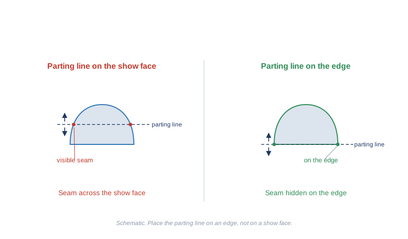
An injection mould consists of two halves that open to release your part. The line where those halves meet is the parting line, and it always leaves a slight mark on your part. So think in advance about where that line should run. Preferably place it on an edge or a less visible surface, not straight across a visible face or a functional fitting surface.
The position of the parting line also determines your draft angles, because both wall halves must taper outward from the parting line. A well-considered parting line keeps your part simple and your mould affordable. That is why it is best to define exactly where the parting line will be together with your mould maker; in co-engineering, you can weigh visibility, release and mould cost against each other in one go.
Source: Envalior, “Draft angle” (shut-off).
Avoid undercuts and recesses
An undercut is a recess, clip or hook that blocks straight release, such as a side hole or a snap finger with a barb. These features are possible, but they require moving mould components (slides), which make the mould more expensive and slower. For a first series, it pays to avoid undercuts where possible or to work around them smartly, for example by designing a clip as an open through-feature instead of a blind barb.

The surface finish of your part
The surface of your part is an exact copy of the mould cavity. Any gloss, matt finish or texture you want on your product is therefore not applied to the part itself, but created beforehand in the steel of the mould. That is why it is best to decide on the desired finish early, as it partly determines how the mould is machined and what it will cost.
Polishing brings the mould cavity to an ultra-smooth, high-gloss mirror finish. Your part comes out glossy, and a smooth cavity also helps with filling and release. Keep in mind, however: a high-gloss finish shows every imperfection mercilessly, so it requires an extra-uniform wall thickness.
Sinker EDM (spark erosion) leaves a fine, uniform roughness in the steel. By varying the process settings, you can achieve different, reproducible roughness levels, from lightly satin-matt to distinctly grainy. Such EDM textures are expressed according to the VDI 3400 standard. A matt EDM texture is also more forgiving: it hides minor flow lines and fingerprints better than a high-gloss finish.

Between these extremes, there are countless finishes, from technical matt to decorative textures, usually expressed as average roughness Ra. The finer or more specific the finish, the more machining the mould requires and the higher the cost. Also remember that a textured surface needs a larger draft angle, as discussed earlier: the deeper the texture, the more draft angle is required.
Common beginner mistakes
Most deformations in an injection-moulded part come down to one cause: plastic that cools unevenly. If you recognise them early, you can solve them in your design instead of through expensive mould modifications.
Sink marks and shrinkage voids
A small dent on the outside (sink mark) or a void inside occurs where the material is too thick. The outside solidifies while the core is still shrinking and pulls material inward. Solution: avoid solid sections, hollow out thick areas and keep the wall thickness uniform. Keeping ribs and thickened features thinner than the wall prevents them from showing through.
Warping
If your part warps after ejection, different areas are cooling at different rates, which builds up internal stress. Solution: use uniform wall thickness and gradual transitions; take extra care with semi-crystalline plastics because they shrink more.
Flow lines and visible weld lines
Where two flow fronts meet, for example behind a hole, a visible or weaker line can form. Solution: keep walls flowing smoothly, avoid unnecessary obstacles and think about where the plastic enters the mould.
Incomplete filling
A thin wall that is too far from the injection point will not fill completely before the plastic solidifies. Solution: do not make walls unnecessarily thin and keep the flow path short. Material choice also plays a role, as some types flow better than others.
Which material suits your part?
For a first series, you usually choose a common thermoplastic that is readily available and easy to process, unless your part has specific requirements such as high temperature resistance, chemical resistance or transparency. ABS is popular for housings, polypropylene (PP) for tough parts with a hinge function, polycarbonate (PC) for impact-resistant and clear parts, and polyamide (PA, nylon) for mechanically loaded parts. If you need more stiffness, fibre-reinforced variants are available.
The exact plastic you need depends on function, temperature and budget. On our injection moulding page, you will find the complete plastics overview with processing temperatures by type.
How much mould do you really need?
Once your design follows the rules of thumb and your prototype has been validated, you reach the step that feels the biggest for a starter: the mould. A full production mould is a substantial, definitive investment, and that is exactly where many first series get stuck. There is a middle way. With a modular mould system, you do not have to have a complete mould built immediately; you only adapt the product-forming inserts. This lowers the threshold for getting your first small series truly injection moulded, with industrial quality instead of a printed prototype.
Frequently asked questions (FAQ)
What wall thickness does an injection-moulded part need?
For most plastics, a workable wall thickness is between about 0.8 and 4 mm, depending on the material. More important than the exact value is that the wall is the same thickness throughout and that transitions are gradual. This prevents sink marks, shrinkage voids and warping.
Why do the walls of a part need to be tapered?
Plastic shrinks as it cools and grips onto the mould. A slight taper in the release direction, known as the draft angle, allows the part to release without damage. A smooth surface may only need half a degree; a textured surface requires more.
Can I have a 3D print directly injection moulded?
Not just like that. A shape that comes out of a printer does not take wall thickness, draft and the parting line into account. You first need to adapt your design to the rules of injection moulding, and that is exactly what this guide covers.
Can you injection mould a 3D printing material such as PLA?
In theory, yes, but PLA is rarely the right choice for a real series because it is brittle and has limited heat resistance. It is better to choose the production material that suits your application right away.
What determines the surface finish of an injection-moulded part?
The mould does. The part exactly reproduces the finish of the mould cavity. Polishing gives a glossy surface, while spark erosion leaves a reproducible matt roughness. So you help define the desired look during the mould design stage.
Where is the best place to position the parting line of a part?
The parting line always leaves a slight mark on the product. Therefore, place it on an edge or a less visible surface, not straight across a visible face or a functional fitting surface. Its position also directly determines your draft angles, because both wall halves must taper outward from the parting line.
Sources
- Envalior, “Wall thickness” — https://www.envalior.com/en-us/wall-thickness
- Envalior, “Draft angle” — https://www.envalior.com/en-us/draft-angle
- PlastikCity, “Material shrinkage rates” — https://www.plastikcity.co.uk/useful-stuff/material-shrinkage-rates
- ISO 294-4, Determination of the shrinkage of thermoplastics
- VDI 3400, Roughness grades for spark erosion textures (EDM)